Understanding Continuous Emissions Monitoring Systems (CEMS): A Comprehensive Guide
A CEMS – or Continuous Emissions Monitoring System – essentially is a system made of several components to retrieve data on emissions and pollutants emitted from a specific source. The Environmental Protection Agency (EPA) requires businesses such as industrial facilities to have these systems to ensure compliance with clean air regulations such as Part 60, 63 & and 75 in accordance with the Clean Air Act.
The Clean Air Act prioritized the reduction of outdoor ambient air pollutant concentrations responsible for issues like smog, haze, acid rain, and more. Additionally, it also aimed to reduce toxic air pollutants causing cancer and health issues while eliminating ozone-depleting chemicals.
This page serves as a guide that gives a closer look at all the components of a CEMS.
Table of Contents
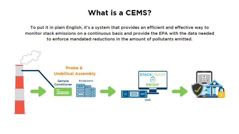
What is a CEMS?
A Full-Extractive CEMS has many components, beginning with a probe inside the stack. These probes are heated, collect the gas sample, and transport it into the umbilical. The umbilical delivers the sample to the CEMS cabinet/rack or shelter. Once the sample is delivered, moisture and temperature levels are regulated before it is introduced to the analyzer(s). Full-extractive CEMS utilizes various gas analyzers to measure certain pollutants and gases. Once the analyzer has measured the sample, it is either released into the atmosphere or sent back to the stack, depending on protocols for that gas type.
Full-Extractive Continuous Emissions Monitoring Systems
Extractive CEMS Flow: How Does It Work?
It is essential to properly control and measure the various flow schemes in your CEMS. Designs and flow settings can vary based on customer preferences, regulatory factors and process conditions. There are several components to a Continuous Emissions Monitoring System (CEMS) operations with their own flow schemes. These are best broken down into:
Sample Flow:
A gas sample originates in the stack and works its way through the system eventually exiting through the CEMS exhaust.
Cal Gas Flow:
Cal gas is introduced into a CEMS at the probe tip and carried throughout the entire system along the same path as the sample. A solenoid is used to control the flow of each bottle. When the solenoid is opened, the cal gas travels through a second valve that allows it to go to the probe or bleed back out the vent. There is one final valve after the bleed valve which is used as a precautionary valve; it serves as a last means to ensure that no cal gas gets through, if one of the initial valves should leak.
Purge Air Flow:
To keep the sample clean and free of particulate build-up, compressed air (purge air) is used to “blow” out the probe periodically. This purge air originates from a customer-supplied compressed or instrument-grade airline. The requirement is 80-100 psig at 8-12 scfm. The compressed air must be oil, particulate, and pollutant-free, with a dewpoint of less than -40°F.
Each of these flows is monitored using flow meters, controllers, and other instrumentation to maintain the proper flow throughout all channels of the CEMS. Our blog post, “Continuous Emissions Monitoring 101: Extractive CEMS Flow Overview” dives into the specifics of how a CEMS flow works.
Let’s Take a Closer Look at CEMS Equipment
Now that we’ve covered the ‘flow’ of a CEM System, we will dive into the equipment from the start of collecting a sample all the way to the end when the excess gas (sample) is purged back into the atmosphere. We will discuss:
- Probes
- Umbilicals
- Sample Conditioners
- Sample Control Panels
- Analyzers
- Calibration Gas Bottles
- Air Clean-Up Systems
- Data Controllers
- Data Acquisition Systems
When working with CEMS, you will likely need assistance with training and maintenance. Explore our CEMSProtect Partner Program if you could use the expertise of seasoned industry experts to assist you in addressing challenges, safeguarding your equipment, and ensuring compliance.
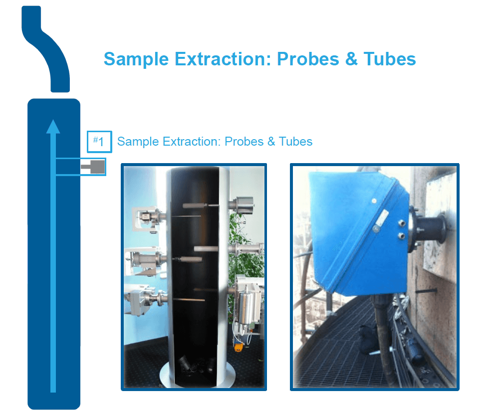
CEM System Probes: Where Emissions Data Begins
As mentioned before, the CEM System Probe serves as the starting point for samples because they undergo transportation and monitoring. Its primary role revolves around preserving sample gases within a controlled, heated environment while eliminating particles before they are introduced into the CEM system.
Main Components of a Probe
- Stinger: The stinger is an extension or pipe at the end of the probe that is inserted into the stack to collect samples. Its size varies based on EPA regulations.
- Mating Flange: This component securely connects the probe to the flange on the stack port. This provides a tight seal to ensure the sample is not compromised.
- Filter Housing: The filter rids the sample of contaminants not wanted in the stream.
- Purge System: The purge system blows compressed air into the probe at fixed intervals to remove any accumulated dust or contaminants.
- Cal Gas Port: This is a port where cal gas begins to flow through the entirety of the CEM system to ensure complete calibration from the beginning of the sample all the way to the analyzer.
- Heater: The heater keeps the sample at proper heat and prevents condensation. The temperature is normally set between 350°-400°F.
If you would like more in-depth information on CEMS Probes, their functionality, and components, read our blog post, “Continuous Emissions Monitoring 101: Extractive CEMS Probes.”
Essential Probe Placement for Precision
The Environmental Protection Agency clearly defines where ports for Continuous Emissions Monitoring Systems (CEMS) Probes, Flow Probes, and Opacity Units should be located on a stack or duct. In order to get good readings from any stack monitoring equipment and pass a Relative Accuracy test, the location where the sample is taken needs to be as representative as possible of the total emissions of the affected facility. These devices monitor emissions, track fluid flow, and assess emission visibility throughout a CEMS.
Locating CEMS Probes, Flow Probes & Opacity Units
- CEMS Probes – CEMS probes are strategically placed at least two equivalent diameters downstream from key points like control devices, where pollutants are generated, or anywhere pollutant concentration or emission rates could change. Additionally, they’re usually positioned at least a half-equivalent diameter upstream from the effluent exhaust or control device.
- Flow Probes – Flow probes are essential for measuring the flow rate of fluids such as water or air, through pipes or channels. You’ll typically find these probes at least eight stack/duct diameters downstream and two diameters upstream from any bends or disruptions in the stack. They ensure accurate tracking of fluid flow.
- Opacity Units – Opacity units gauge how visible emissions are by measuring light blockage. They should be placed at least four duct diameters downstream from particulate control equipment or areas with flow disturbances to ensure accurate readings. They should also be positioned two duct diameters upstream from flow disturbances in the absence of condensed water vapor, and accessibility for maintenance is crucial.
- Watch our CEMS Equipment Maintenance How-To Series that discusses the operation, components and common maintenance for the Teledyne Monitor Labs Lighthawk 500 Opacity Monitor.
By strategically placing these probes, you can effectively monitor emissions, track fluid flow, and assess the visibility of emissions, contributing to a more efficient operation at your facility. For more insight on this subject, read our blog post, “CEMS Probes, Flow Probes, & Opacity Units: How To Locate.”
Importance of CEMS Probe Maintenance: Extending System Lifespan
Since CEMS probes are the first contact with samples in your CEM System, it is important that you perform regular maintenance to ensure that your probe performs effectively for the longest time possible. The following are some of the best practices for CEMS Probe maintenance to be completed annually for Extractive and Dilution Probes.
Extractive System Probes
Extractive system probes often face issues such as loose umbilical connections or leaking O-Rings. Here are some ways to troubleshoot your extraction system probe:
- Power Down: First things first, switch off the extraction pump. This step ensures your safety and prevents any mishaps during the troubleshooting process.
- O-Ring Check: Loose umbilical connections and O-Ring leaks can be common issues. To tackle this issue, carefully remove the filter lid and replace both O-rings. This should help seal any leaks and ensure a snug fit.
- Filter and Flat Packing: It’s time to address the heart of your extraction system probe. Replace the filter and flat packing. This step can significantly improve the performance of your system.
- Power Up: With everything securely in place, go ahead and turn on the extraction pump. Make sure to do this after addressing the previous steps to avoid any unexpected issues.
- Auto-Calibration: To wrap things up, run a hands-free auto-calibration. This final step fine-tunes your extraction system probe, ensuring it’s ready to deliver accurate results.
Dilution System Probe
Maintaining a fully functional dilution system probe is key to consistent and reliable performance. To prevent issues like cracked or clogged critical orifices and stinger tubes, follow these straightforward steps to keep your probe in top shape:
- Pause the Probe: Start by turning off the probe air. This step ensures safety and allows you to work on your dilution system probe without unexpected mishaps.
- O-Ring Check: To address potential leaks, remove the filter lid and replace both O-rings on the lid. This simple action can go a long way in maintaining a tight seal.
- Filter and Flat Packings: The filter and flat packings are crucial to the probe’s functionality. Swap them out to keep your dilution system probe operating smoothly.
- Rebuild Cross or Dilution: If you suspect issues with cross or dilution, it’s time for a rebuild. This step can resolve many common problems and extend the life of your system.
- Resume Probe Air: With all the components securely in place, it’s time to turn the probe air back on. This action reactivates your system, and it should be done after the previous steps to avoid any complications.
- Auto-Calibration: Finally, run a hands-free auto-calibration. This final touch ensures that your dilution system probe is finely tuned for optimal performance.
There’s always room for more maintenance on your Full-Extractive CEM System. Read more on The Importance of CEMS Probe Maintenance on our Source Blog.
Watch our video discussing the M&C SP2006 Dilution Probe. In this video, we cover basic operation, major components, and the most common maintenance events, including replacing the probe filter, and rebuilding the dilution and eductor blocks.
CEMS Umbilical: The Lifeline of Gas Samples
Another crucial component of a CEMS is the umbilical. The continuous emissions monitoring umbilical is a bundle of pneumatic tubes and electrical wires used to interconnect the probe, the gas analyzers, and the gas transport system. This tubing system allows gas samples to travel from the emission source throughout the entire CEM System. This is a system with several possible issues that require routine checks and maintenance to prevent. For help with umbilical inspection or maintenance, visit our Umbilical System Inspection Service page.
Main Components of an Extractive CEMS Umbilical
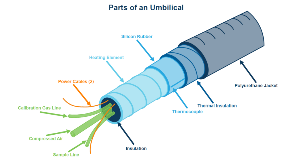
- Wiring: The umbilical system includes control wiring for the stack J-box and the AC voltage for the pride and umbilical heaters.
- Tubing: The sample tubing is the core of the umbilical that carries the gas samples. The material for these is normally Teflon but can vary depending on the specific application’s requirements for keeping the sample at the proper temperature. Another common material for umbilical tubing is stainless steel.
- Insulation/Jacket: Insulation reduces heat loss and protects the tubing from external conditions and damage. The jacket similarly provides a protective covering, shielding the umbilical from damage.
- Heater: Heater nodes run along the umbilical every three inches and usually keep temperatures set between 250° and 350°.
Common CEMS Umbilical Failures
Heater cables run nonstop and constantly expand and contract. This cable connects from a series of tubes and wires to the sample probe at the top of the stack or duct to the CEMS Shelter on the ground. It is important to routinely inspect your heater cables to verify they are the proper heat at multiple points.
The PID thermostat controller should hold a stable temperature within plus or minus 5 degrees at the set point. Malfunctioning thermostats can cause melting in the umbilical bundle, so temperatures should be monitored closely and regularly.
Buildup in sample and calibration lines can cause your entire umbilical system to fail. These lines should be regularly inspected and flushed as needed to avoid this failure.
Several different scenarios can cause kinks or damage to the bundle. You should be aware of your cable trays and ensure the umbilical hasn’t shaken out or had its zip ties cut away by a subcontractor.
As the Teflon tubing material ages, it will break down, especially when exposed to outdoor elements. This can cause gas leaks and vacuum reading errors in dilution probes. To avoid this failure, regularly inspect your tubing. In addition, have it freshly cut with new lock fittings every 5 to 10 years.
To avoid stressed tubing in the probe box, it is important to heat-shrink the boot after installation. This reduces the amount of stress and the connections in the probe box from the weight of the bundle underneath.
Winter is a rough time for umbilical assembly because sample and cal lines are susceptible to freezing. If you install your system in the winter, ensure that your umbilical is heating uniformly from end to end.
Excess moisture can cause serious damage to your umbilical system, and you should perform checks weekly to detect any moisture buildup. Also, be positive that sufficient dry instrument air is provided to avoid this.
Read “Continuous Emissions Monitoring 101: Extractive CEMS Umbilical” for a breakdown of CEMS Umbilicals and the required maintenance.
CEMS Filters: Ridding Your System of Harmful Materials
When dealing with CEMS, it is necessary to understand the importance of filters. CEM system sample probes commonly incorporate external and internal filters to prevent particulate matter from entering and contaminating gas samples. Filters should be checked once every six months at the very least. By practicing this maintenance, you can keep your CEMS clean and extend the life of your equipment. Take a look at your filters; if they look like a grey cat, it’s time for maintenance! Read up on why checking your filters is key to a functioning CEM system.
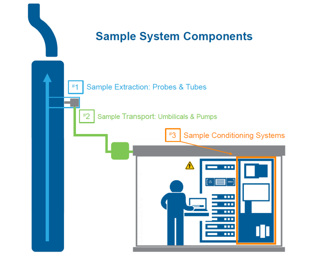
Sample Conditioner: Preparing Samples for Analysis
So the sample has passed through the probe, the umbilical line, and now it is at the CEMS shelter, almost ready to be analyzed, but before a sample can be transported to the analyzer, it must go through a sample conditioner to remove any moisture or harmful material that will cause damage.
Main Components of a CEMS Sample Conditioner
- Peltier Cooler: This is a heat pump that transfers heat from one side of the device to the other.
- Sample Pump: This pump creates a vacuum that draws the sample from the stack.
- Peristaltic Pump: A dual pump that is used to remove moisture that condenses out of the sample.
- Filter: After passing through the sample conditioner there is a final filter before it enters the analyzer.
- Flow Meter: Adjusts the sample flow throughout.
- Water Carryover Sensor: This sensor detects moisture breakthrough if the sample conditioner fails to remove any and sends a signal to the Data Acquisition System.
Common Sample Conditioning Failures
If the ambient temperature level in your sample conditioning system is too high or too low, it can cause various operation issues such as gas chiller malfunctions in the summer or freezing in the winter. To prevent this, usage of both compressor-style and Peltier-style gas coolers is recommended.
Impingers and heat exchangers are susceptible to freezing, which can be identified by ice coating on the exterior. To avoid this, the functionality of the thermostat and boards must be monitored often.
The peristaltic pump requires regular maintenance to prevent corrosion and damage over time. The frequency of rebuilding depends on the system and nature of the chemicals present.
This is important to keep an eye on to avoid compromising samples in your system. The small wheel within the pump turning smoothly and operating silently is a good indicator of proper functionality. This should be closely monitored along with the tubes which can fail often.
In colder months, the condensate drain can freeze, leading to issues with moisture management. You should regularly check the drain, slip sensor, and relays to prevent this freezing and any moisture buildup
Excessive aerosols and particulate matter can clog filters, sample lines, and impingers. Specialized filters can prevent this, but adjustments to the system might be required over time.
This sensor is very important, as it shuts down the system if it detects any moisture. This prevents any moisture from reaching the analyzer and if it fails it could be severely detrimental to your system.
This issue is characterized by a surplus of condensate that the pump struggles to evacuate quickly enough. Room temperature/humidity, worn-out pumps, or changes to the system can all be causes of this.
Any change to process conditions such as increased moisture content or higher inlet temperatures can overwhelm the system. Avoid this by opting for a robust and versatile sampling conditioning system and making adjustments as needed.
To guide yourself through this system, its functionality, and its components, utilize our blog post on “Continuous Emissions Monitoring 101: Sample Conditioning Systems.”
Schedule CEMS Sitewalk & Evaluation
We offer a four-step evaluation process where we visit your site, assess all of your CEMS equipment, source additional equipment for repairs or upgrades, and professionally install these new components.
CEMS Analyzers: Measuring Emissions
CEMS Analyzers are specialized instruments for measuring the concentrations of various pollutants and gases in air emissions. There are various types of specialized analyzers designed to measure specific gases, including NOx, SO2, CO, CO2, O2, THC, NH3, and more. Each gas-specific analyzer employs particular technologies, such as Chemiluminescence, Pulsed Fluorescence, NDIR (Non-dispersive Infrared Sensor), FTIR (Fourier-transform Infrared Spectroscopy), FID (Flame Ionization Detector), and Zirconium Oxide. Read more about CEMS Analyzers: What They Are and How To Maintain Them.
We provide a comprehensive range of analyzers and their associated sampling components from multiple suppliers. Additionally, we offer services for analyzer repairs, upgrades, and maintenance.
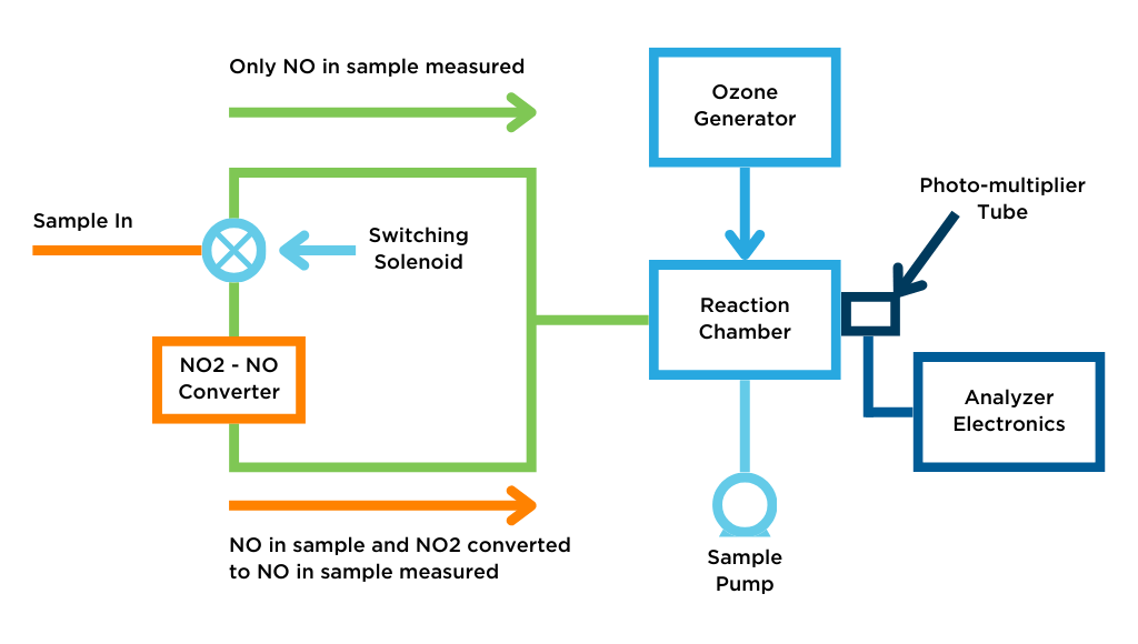
NOx Analyzers: Chemiluminescence Technology
NOx Analyzers measure concentrations of nitric oxide, total oxides of nitrogen, and nitrogen dioxide through Chemiluminescence technology. However, the chemical reaction that this analyzer utilizes only works with NO and not NO2, so all gases must be converted to NO before measurement. When samples enter a reaction chamber, their luminescence, and NO levels can be calculated.
Dive deeper into the functionality and preventative maintenance required in our CEMS 101 Series: NOx Analyzers.
Watch our video in our CEMS Equipment How-To Series on YouTube about the Thermo Scientific 42iQ NO-NO2-NOx Analyzer. We will identify the basic layout and the tools to perform the recommended preventative maintenance.
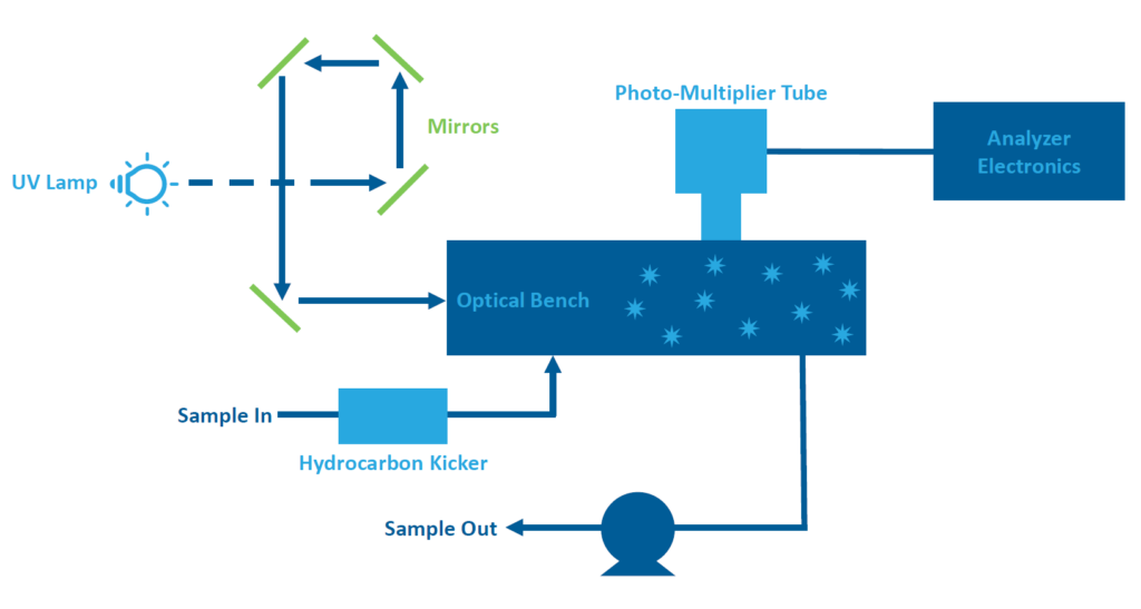
SO2 Analyzers: Pulsed Fluorescence Technology
When working with Sulfur Dioxide SO2 gases, analyzers are constructed using Pulsed Fluorescence technology. This technology offers the best sensitivity for SO2 measurement since SO2 molecules absorb ultraviolet (UV) light.
As the UV light travels in the reaction chamber where the SO2 is present, the SO2 molecules fluoresce and are measured by a photo-multiplier tube (PMT). The PMT detects the UV light emission from the SO2 molecules and sends out a voltage signal, which is calibrated to the amount of SO2 present.
Learn more about how this analyzer type functions and the maintenance required in our CEMS 101 Series: SO2 Analyzers.
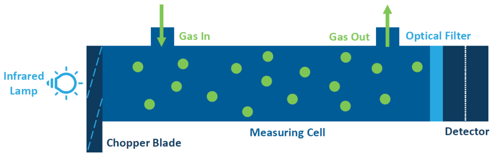
CO Analyzers: Infrared Radiation for Accurate Measurements
CO Analyzers utilize infrared radiation to measure concentrations for this gas type. Since Carbon Monoxide absorbs infrared radiation, light can be reflected through the system to determine CO levels in the sample. NDIR analyzers (CO Analyzers) incorporate a single-beam photometric system and a detector with a microflow sensor.
The instrument consists of an infrared light source, a chopper, a measuring cell, and a detector filled with a gas mixture containing the gas component to be measured. Interested in learning more about how NDIR and CO Analyzers work?
Read more about their components and preventative maintenance in our CEMS 101 Series: CO Analyzers.
O2 and Flow Analyzers
For measuring Oxygen with a Continuous Emissions Monitoring System (CEMS) the most reliable and simplest method is utilizing a zirconia cell. For measuring flow with a CEMS, the most reliable and simplest method is utilizing an S-type Pitot Tube system. This is the same technology stack-test crews utilize and is the EPA reference method.
Read more about their principle of operation and applications in our CEMS 101 Series: Oxygen & Flow Analyzers.
Portable Gas Analyzers: On-the-Go Measurements
Portable Gas Analyzers are a convenient tool for making approximate measurements of concentrations in hot-wet exhaust streams. Due to technological limitations, they are not as accurate as CEMS analyzers but can still be useful in certain situations. The specific technologies used for these analyzers vary depending on the type of gas being measured or the term length of measurements. The most common technology used for portable analyzers is electrochemical. For more on the different types of portable analyzers and the technologies they use, read “Portable CEMS, The Search for Accuracy.”
Obsolete Analyzers and When to Replace Them
CEMS Analyzers play a vital role in regulatory compliance for your facilities. With constant technological developments and changing regulations, older CEMS analyzers can become obsolete and harder to maintain. This can pose risks to both compliance and operational efficiency, so it’s important to identify if your analyzers are obsolete and if upgrading yours is the right move for your facility.
For more information on obsolete analyzers and reasons why you should upgrade yours, read our blog post: “Are your CEMS Analyzers Obsolete?”.
Analyzer replacement and compliance testing under 40 CFR Part 75 are complex processes requiring careful planning and execution. For a guide on this, read “Best Practices for Replacing Your Analyzers Under Part 75”.
Sample/Calibration Control Panel: Managing Gas Flows
The Sample/Calibration Gas Control panel controls the sample and calibration gas flow to the analyzers and probe. These panels can come as mounted cases or plates with components mounted behind them. This component can easily be replaced intermittently over the life of the CEMS.
Main Components of a Gas Panel
- Solenoids: These are devices that help manage the flow of gases by opening and closing gas flow paths and switching between sample sources.
- Rotameters: This device measures and controls the flow rate of gases through the CEMS.
- Gauges: Device that measures the pressure of gases within the sampling system.
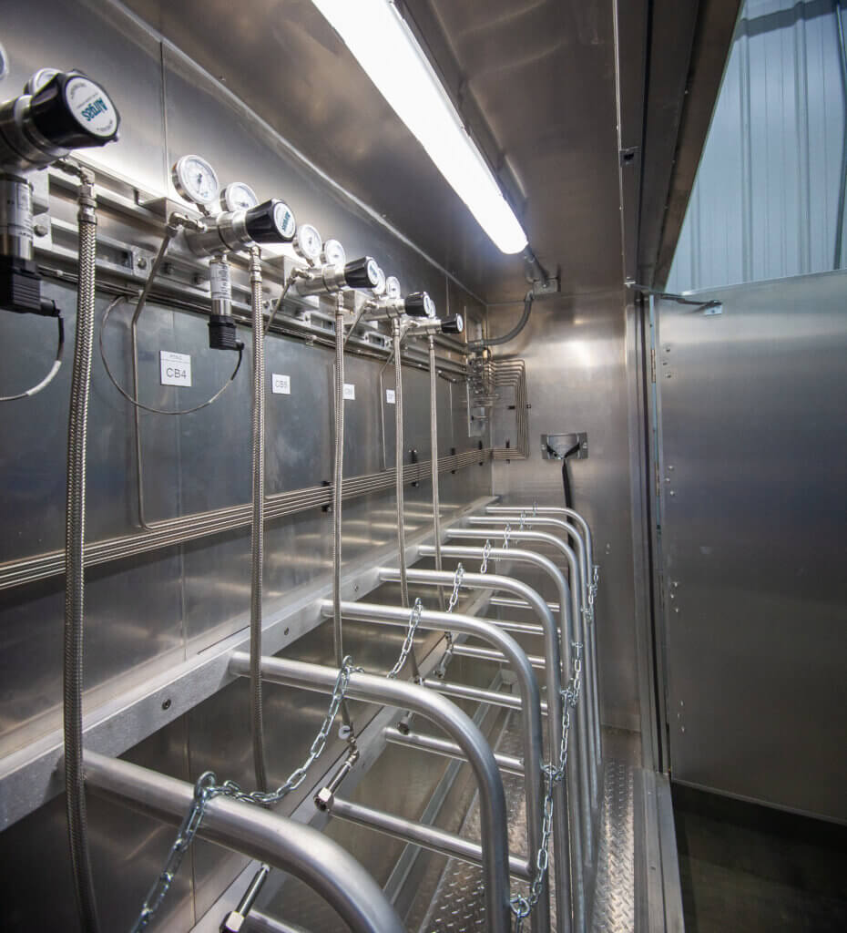
Calibration Gas Bottles & Requirements
The cal gas is introduced as close as possible to where the sample gas enters the system so that it can flow through the same path as the sample gas. For a CEMS, this means that the cal gas is sent up the umbilical and introduced at the front of the probe, where it then travels the same entire pathway as the stack gas down to the analyzers.
Cal gas comes in various configurations, blends, and concentrations depending on the CEMS requirements. Typically CEM Systems use blended bottles to both save money and streamline the calibration time. Many gases can be blended together and remain stable.
Calibrating a CEMS can become very complex. Dive into our CEMS 101: Calibration and Gas Requirments blog post for more detailed information.
Daily Calibration Checks
On a daily basis, a Part 60 CEMS must pass within 10% of the cal gas bottle concentrations. More than 10% error is considered a failed cal. There is also a “bad” cal designation, which is a cal error that is greater than 5%, but less than 10%. A CEMS is allowed 4 bad cals in a row, after which it’s considered a fail.
A Part 75 CEMS must pass within 5% error on a daily basis. In either system, if dual range analyzers are used, BOTH ranges must be checked. A failed cal typically requires operator intervention to adjust the analyzer.
Air Clean-Up Systems
Full-extractive CEMS requires instrument-grade air to be brought in to purge the probes, gas lines, and analyzer cases of any interfering gases that might get into them. Air Clean-Up Systems ensure that the instrument air supplied is clean and moisture-free. These systems are often located in the CEMS cabinet or wall-mounted nearby. Quarterly maintenance is required for these units to ensure sufficient functionality and replace any faulty parts.
Main Components of an Air Clean-Up System
- Coalescing Filter/Auto-Drain: This is where the instrument air is first introduced and any moisture is removed.
- Canister with Drierite: Next, the air is moved into a canister filled with drierite. The air then travels up through the drierite which turns from blue to pink if it absorbs any remaining moisture.
- Coalescing Filter/Manual-Draw Filter: This filter works similarly to the initial one, but requires manual drainage.
- Canister with Purafil (NOx and SO2): Air then moves into a canister with Purafil. Purafil absorbs the NOx and SO2 in the instrument air and turns from pink to brown when it absorbs the two gases. This is only used if NOx and SO2 are being measured.
- Canister with Charcoal (THC): If a dryer is being used or hydrocarbons are being measured, a canister with charcoal is used to remove any hydrocarbons in the instrument air.
- Dryer Towers (CO2 & Moisture): These are two towers that are used to absorb any moisture still in the instrument air. The air must be hydrocarbon and oil free for the dryer towers to function.
For a crash course on this subject, read “Continuous Emissions Monitoring 101: Air Clean-Up Systems” on our source blog.
What is a Data Controller’s Role in a CEM System?
Data controllers (also known as data loggers) are the hardware bridge between a data acquisition system and an emissions monitoring rack. The data controller continuously collects and validates air emissions monitoring data and sends it to the software for calculation, monitoring, and reporting. The data controller continuously collects data from multiple sources in a facility.
ESC Spectrum’s family of 8864 Data Controllers excel at collecting, monitoring, conducting Quality Assurance, and reporting on emissions data from continuous monitoring systems with pinpoint accuracy. Read more about best practices for operating our 8864 Data Controller and it’s role in our blog post, 8864 Data Controller Best Practices.
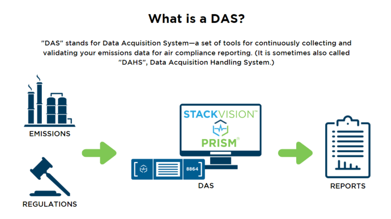
Choosing a Data Acquisition System for Your Facility
A Data Acquisition System (DAS) – also known as a Data Acquisition and Handling System (DAHS) – is a set of tools for continuously collecting and validating your emissions data for air compliance reporting. It is a critical component of your facility’s Continuous Emissions Monitoring System (CEMS). They are most commonly made of two components: the Data Logger (PLC) or the Server (PC). ESC Spectrum’s Data Acquisition Systems, such as StackVision, Prism, or CEMDAS are industry-leading software systems around the U.S. Contact us today to receive a demo from our experts.
Air Emission Regulations
If you want to learn about environmental compliance and the EPA regulations for air emissions at your facility, ESC Spectrum offers a wealth of articles for all air emissions regulations you can find in our Definitive Guide to Air Emissions Regulations. This guide will help you on your journey to mastery of environmental compliance.
The Definitive Guide to Air Emissions Regulations
Ensuring CEMS Optimization and Compliance
Maintaining Continuous Emissions Monitoring Systems (CEMS) is crucial to minimize downtime, prevent costly repairs, and ensure the integrity of emissions data reported to regulatory agencies. Here are five tips to ensure accurate and reliable monitoring:
1. Regular Calibration and Linearity Checks
Conducting regular calibration and linearity checks is essential to maintain the accuracy of emission monitoring requirements. Calibrate gas analyzers and other monitoring instruments according to manufacturer specifications and regulatory requirements.
2. Routine Inspection and Cleaning
Regular inspection and cleaning of CEMS components help prevent the buildup of dust, debris, or contaminants that could affect measurement accuracy.
3. Scheduled Maintenance and Service
Implement a scheduled maintenance program to address routine servicing and preventative maintenance tasks for CEMS equipment. Follow manufacturer recommendations for maintenance intervals and procedures. Service components such as pumps, valves, heaters, filters, and flow meters according to their specified maintenance schedules.
4. Data Validation and Quality Assurance
Establish data validation and quality assurance procedures to ensure the integrity and reliability of emissions data collected by your plant’s CEMS.
5. Training and Personnel Development
Invest in training and development programs to ensure that your team responsible for operating and maintaining your facility’s CEM System is competent and knowledgeable.
Read our blog post, 5 Tips to Help You Maintain Your CEM Systems, for more detailed explanations of the tips listed above.
Monitoring Plans for CEMS
A monitoring plan consists of several key components that ensure accurate monitoring and reporting. These components include compliance with specific programs, reporting frequencies, emission units, emission points, monitoring systems, pollution control devices, and additional monitoring requirements. The plan is site-specific, tailored to each installation, and should be continuously reviewed and updated to reflect current operations accurately.
Monitoring plans can vary depending on the type of unit and specific requirements. Some examples include full CEMS, Appendix D, and Appendix II. Full CEMS are commonly used in coal plants and involve monitoring multiple emissions, such as SO2, NOx, and stack flow. Appendix D offers optional monitoring for certain emissions, allowing calculations based on fuel flow. Appendix II presents an alternative protocol for calculating NOx emissions using relevant data.
Whether you are familiar with monitoring plans or new to the concept, read our blog post for a high-level overview of their significance, components, and upcoming changes.
QA/QC Manuals
If you have a CEMS or COMS compliance system, make sure to have a QA/QC manual to go alongside it. It is essential to review the plan and ensure regular updates are made as your CEMS and COMS change.
Read our blog post, QA/QC Manuals: What You Need to Know, for a better understanding of what the EPA requires at your facility.
Our Software & Hardware for CEM Systems to Remain in Compliance
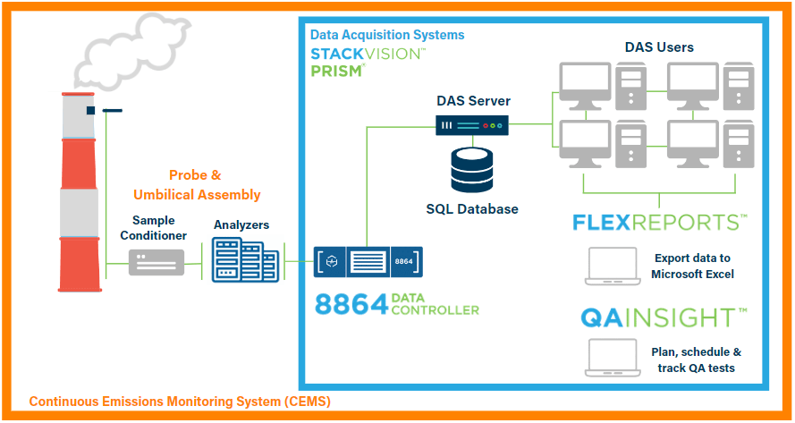
The industry-leading 8864 Data Controller provides reliable, robust data collection, computation, and storage capabilities. It is the most widely used device for air emissions data from Continuous Emissions Monitoring Systems (CEMS) in the U.S.
ESC Spectrum provides three different Data Acquisition System choices – StackVision, Prism, and CEMDAS.
Easily and securely export data from StackVision into Microsoft® Excel for maximum flexibility with FleXReports software.
Schedule, plan and track activities related to performing Quality Assurance (QA) tests with QAInsights software.
CEMS Retirement
Retiring a Continuous Emission Monitoring System is a significant undertaking for any facility. Although there has been a decrease in the amount of units retiring compared to the previous decade, it remains a critical process that a lot of facilities will need to carefully plan and execute. This process involves equipment removal, building demolition, server storage, and properly submitted Emission Data Report (EDR) files.
To learn more about the unit retirement process, read our blog post: “Retiring a CEMS: Ensuring a Smooth and Secure Process for Your Facility”.
Planning Ahead: CEMS Checklists
CEMS In A Nutshell
As you can see, there are several factors and components that contribute to the functionality of a CEMS. All components look differently across different systems and require unique maintenance to avoid failures. To stay educated and up to date on CEMS and industry best practices, make sure and utilize the wide variety of content on our Source Blog.