Measurement of Sulfur Dioxide
While more than one Analyzer technology is available for measuring various Continuous Emissions Monitoring Systems (CEMS) gases, a long history of experience has shown that certain technologies lend themselves better to specific gases. In this case, we look at using Pulsed Fluorescence technology to measure Sulfur Dioxide (SO2).
Pulsed Fluorescence offers the best sensitivity for low range Sulfur Dioxide (SO2) measurement and is the most common method used today. Pulsed Fluorescence operates on the principle that SO2 molecules absorb ultraviolet (UV) light and become excited at one wavelength, then decay to a lower energy state emitting UV light at a different wavelength. In other words, there is a measured difference in how much UV light is created based on how much SO2 is present in the sample (SO2 fluoresces).
How Does the Sample Move Through the Analyzer?
The sample is drawn into the analyzer through the sample bulkhead. The sample first flows through a hydrocarbon “kicker,” which removes hydrocarbons from the sample by forcing the hydrocarbon molecules to permeate through a special tube wall (tube inside a tube). The SO2 molecules pass through the “kicker” unaffected. The reason for the kicker is that hydrocarbons can quench the UV fluorescence and will lower the SO2 readings. In many applications where hydrocarbons are not present or minimal in concentration, the kicker is not included in the analyzer.
The sample flows into a fluorescence chamber, where pulsating UV light causes the SO2 molecules to fluoresce. The pulsating UV light is directed into a mirror assembly. The mirror assembly contains four selective mirrors (bandpass filters) that reflect only the wavelengths which excite SO2 molecules. The four-mirror assembly is actually two sets of two bandpass filters. (Mirror A1 to Mirror B1 to Mirror A2 to Mirror B2)
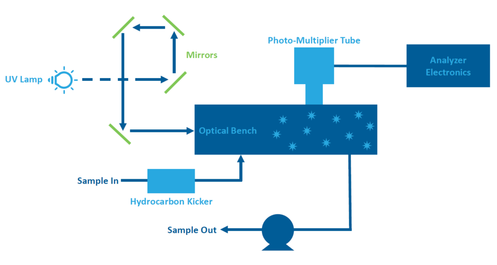
As the UV light travels in the reaction chamber where the SO2 is present, the SO2 molecules fluoresce and are measured by a photo-multiplier tube (PMT). The PMT detects the UV light emission from the SO2 molecules and sends out a voltage signal which is calibrated to the amount of SO2 present. A photodetector located at the back of the fluorescence chamber continuously monitors the pulsating UV light source. The UV light constantly receives an increasing or decreasing voltage based on the photodetector’s reading. This helps maintain a relatively constant intensity at all times.
The UV source is pulsed 10x/sec for timing and bursts of a more intense, brighter light, allowing a better signal-to-noise ratio. As the sample leaves the optical chamber, it passes through a flow sensor, a capillary, and the “shell” side of the hydrocarbon kicker. It then proceeds out the exhaust through the pump. An internal pump is needed as the hydrocarbon kicker works under a vacuum.
Connections & I/O
Like other analyzers, SO2 analyzers have four basic connections (typically in the backplane). There is a sample inlet, a sample exhaust, a power connection, and a signal wire connection (usually an analog output corresponding to the sample value). Either a 4-20mA or 0-10V analog signal output is commonly used. Many analyzers include digital outputs for alarm conditions, etc. Newer analyzers have an Ethernet output for direct communication with a PC.
Maintenance & Preventative Maintenance (PM) Tasks
Preventative Maintenance
Preventative Maintenance is recommended quarterly with any SO2 Analyzer:
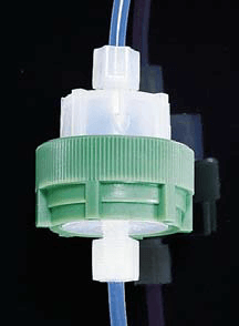
- A good practice is to install a final protective Teflon filter just before the analyzer inlet. The picture to the right shows a typical Teflon filter holder, which holds a Teflon disk. This filter holder is simply unscrewed for filter replacement. This filter should be changed quarterly.
- The status of components can usually be checked through various menus on the analyzer display. Some features display gain and pressure, etc. It is a good practice to record various analyzer values in a daily log. These can be checked for trends as different components start to fail or as an analyzer starts to plug. This log becomes invaluable for troubleshooting.
- Chassis filters and/or fan screens should be cleaned every quarter to keep dust from accumulating and building up inside the analyzer case. For more information, read The Key to Efficient CEMS Equipment: Check Your Filters.
- ESC Spectrum has many resources on PM, including blog posts such as CEMS Analyzers: What They Are and How to Use Them.
Additional Maintenance
There is some additional maintenance specific to an SO2 Analyzer:
The first mirror (bandpass filter) in the mirror assembly typically needs to be replaced after 2 years. This mirror degrades due to the constant bombardment of UV rays – being the first mirror in the series, it takes the bulk of the radiation damage. The other mirrors typically do not degrade.
Trouble zeroing the analyzer is a good indicator that the mirror is nearing the end of its life. The mirrors are locked in a housing that makes them simple to pull out and change. The UV bulb typically lasts 2-3 years and then needs to be replaced.
PM Tasks
There are other PM tasks that are done on an annual basis.
- The pump should be rebuilt with a diaphragm and valve replacement kit. This is inexpensive insurance.
- Bearings should be inspected. Rather than replace bearings, it’s easier to replace the entire pump.
- Replace capillary o-rings and clean or replace capillaries.
How ESC Spectrum Can Help
Interested in learning a more comprehensive overview of how CEM Systems work? Read Understanding Continuous Emissions Monitoring Systems (CEMS): A Comprehensive Guide. This guide will give you a complete understanding of all the components in the flow of a CEMS.