Oxygen Analyzers
For measuring Oxygen with a Continuous Emissions Monitoring Systems (CEMS) the most reliable and simplest method is utilizing a zirconia cell. When a zirconium oxide disc is heated above 600 ̊C and two different concentrations of oxygen are passed on each side of it, an electric potential is generated which can be measured across the disc.
On each side of the zirconium oxide disc are platinum electrodes to provide the conductive surface needed. A reference gas (usually instrument air or simple ambient air at 20.9% O2)

flows across the inner electrode and the sample flows across the outer electrode. A voltage is created and measured. This voltage is proportional to the concentration of oxygen present in the sample and displayed on the analyzer.
Maintenance
Because of the simplicity of the technology (no moving parts), a zirconia O2 analyzer requires very little maintenance – typically just calibration as needed to ensure accurate readings. The zirconia disk can have a long life (typically 5-7 years or more depending on the application). Unlike an electrochemical cell, it does not dry out or change its response characteristics with use.
Because of the high temperatures that the zirconia cell operates at, it can also be used for in-situ measurement (i.e. located in a wet sample stream). This makes it a useful technology for measuring both wet and dry oxygen levels. To learn more about CEMS maintenance, click here.
Flow Analyzers
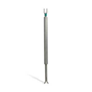
For measuring flow with a CEMS, the most reliable and simplest method is utilizing an S-Type Pitot Tube system. This is the same technology utilized by stack-test crews and is the EPA reference method.
Applications & Principle of Operation
A flow monitor is required when two conditions exist: one, compliance terms state the customer must report in mass emissions, and two, no fuel flow signal can be provided by the customer to calculate the mass emissions. With some applications (i.e. coal, wood-burning plants, etc.) flow monitors are required to calculate the mass emissions, but with others (typically gas or oil burners) a fuel flow signal can be provided to the DAS.
The accurate measurement of both air velocity and volumetric airflow can be accomplished using an S-Type Pitot tube. The Pitot tube measures air velocity by measuring the difference between the pressure generated by the total pressure (lower tube) and the static pressure (upper tube). Inputting the temperature measured using an RTD and the ΔP into Bernoulli’s equation allows the velocity to be calculated. The average velocity is then multiplied by the stack cross-section to determine the volumetric flow.
S-Type Pitot tube seen right.
Key Components
- Differential Pressure Switch: The differential pressure switch is used during the daily span check. It can be adjusted to trigger when a certain ΔP is measured.
- Type S Pitot Tube: The pitot tube is typically hastelloy, but the flange and supports, if needed, are stainless steel. Alternate materials may be required for temperatures over 1000°F.
- Temperature Sensor Transmitter: A RTD is used in the stack to measure temperature. A signal is sent to the temperature transmitter. The transmitter sends this to the controller to calculate the flow.
- Manometer: The manometer uses red gage oil. Through the use of a pitot tube connected differentially to the manometer, the ΔP is indicated in inches of H2O. This is a primary standard for calibration.
- Pressure Transducer: The pressure transducer senses differential pressure. It has two lines coming in from the solenoid setup (one for the high and one for the low). The output is an analog 4 – 20 mA signal.
Operation
Like any CEMS analyzer, there are four main operating modes: measurement, zero cal, span cal, and purge.
Measuring Mode
Tubes run from the stack high side and the low side of the Pitot tube into the flow cabinet. Each of these lines is brought into the cabinet in parallel with the ∆P transmitter and manometer. The manometer can be valved in to indicate the pressure visually. The pressure transducer sends a 4-20mA signal of the pressure differential to the controller.
Constant purge is utilized to keep the pitot from plugging and to keep it dry. The instrument air brought in (60- 100psi) is reduced down by two pressure regulators to approximately 2 psig before it is brought to rotometers that control the purge air to both the high side and low side of the pitot tube. The flow of the air is very low so that it doesn’t affect the pressure being measured. The rotometer only has a range of 0-50 cc/min. The air continuously flows through the lines to keep any stack deposits or dust from getting in it (a constant purge).
Zero Mode
Both the high side and the low side paths from the stack are opened to ambient. Since the pressure is the same on both sides when it is brought to the manometer and the transducer, the reading should be zero (differential pressure).
Span Mode
Both of the paths are cut-off from the stack. The low side is opened up to ambient (known value). The high side is set to a higher pressure so that the span can be measured. A couple of steps are taken by the flow monitor to set the high side.
The instrument air brought in goes through the two regulators that the continuous purge air goes through, plus one additional regulator that brings it down to 10” w.c.. The pressure is reduced further using a needle valve.
The air is “bottled up” to be measured by the manometer and pressure transducer. A line is also run to the pressure differential switch. When it reads the ΔP that it was set for, it shuts down all of the solenoids controlling the high pressure for the span, thus bottling the air up to provide a constant pressure to compare the calibration to each cycle.
Purge Mode
The instrument air is brought in and reduced to 35 psig with a second regulator in its path. The path is then opened for it to blast through the sensor lines and into the stack – keeping them clean and unclogged.
Maintenance
The flow monitor requires preventative maintenance (PM) on a quarterly basis.
- The flow monitor’s pitot tube is pulled out of the stack and brushed clean of any stack dust. The port is also brushed cleaned at this point.
- A Part 75 requirement is that a pressure test be done, but this is typically done on all systems with a flow monitor. This pressure test is typically built into the flow monitor.
- Read more about CEMS Probes, Flow Probes, & Opacity Units.
How ESC Spectrum Can Help
Interested in learning a more comprehensive overview of how CEM Systems work? Read Understanding Continuous Emissions Monitoring Systems (CEMS): A Comprehensive Guide. This guide will give you a complete understanding of all the components in the flow of a CEMS.