Extractive CEMS Probes
The continuous emissions monitoring probe is the initial contact with the sample being drawn for monitoring. It is also the separation point of the sample gas, purge air, and cal gas. Its primary function is to provide a heated environment to maintain sample gas temperatures above the stack dewpoint and remove particulate material from the gas sample.
Construction of the Extractive CEMS Probe
The probe is constructed to serve three primary purposes:
- Keep outside air from being introduced into the sample (i.e., keep the sample air-tight)
- Keep the sample at a temperature high enough to prevent condensation (the formation of water droplets in the system)
- Allow for a point of cal gas introduction into the CEM system
The CEMS probe is housed in a NEMA 4 box. Type 4 enclosures are intended for indoor or outdoor use primarily to protect against windblown dust and rain, splashing water, and hose-directed water; and to be undamaged by the formation of ice on the enclosure.
Main Components and Purposes
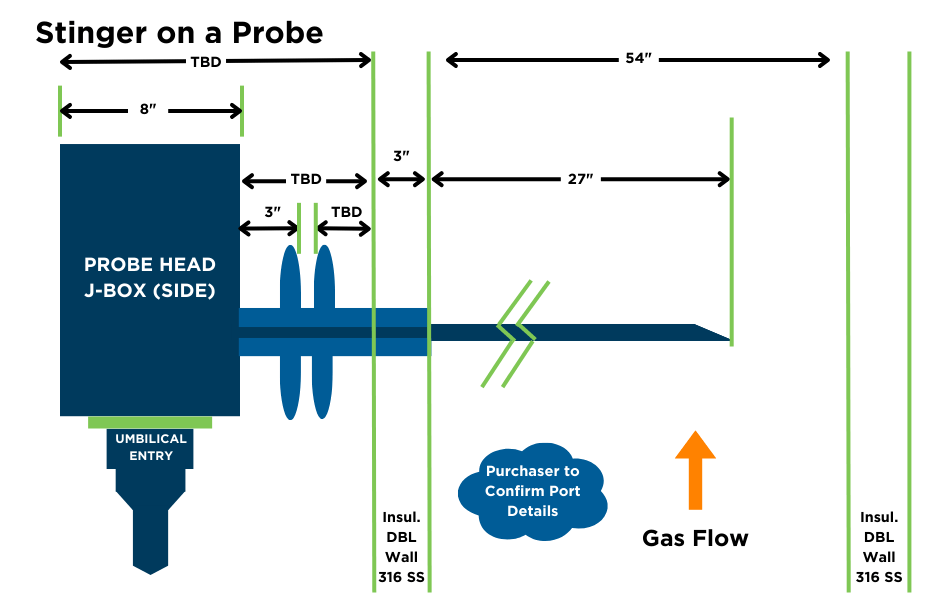
The stinger is a pipe made of either stainless steel or Hastelloy (material selected based on application and presence of corrosive gases) that extends into the stack from which the sample will be collected.
The Stinger has an angled end oriented in the stack facing up to prevent moisture and dirt particles from direct impingement (see drawing).
The length of the stinger is determined by regulations requiring that it protrude into the stack’s midpoint or 1-meter minimum (PS-2).
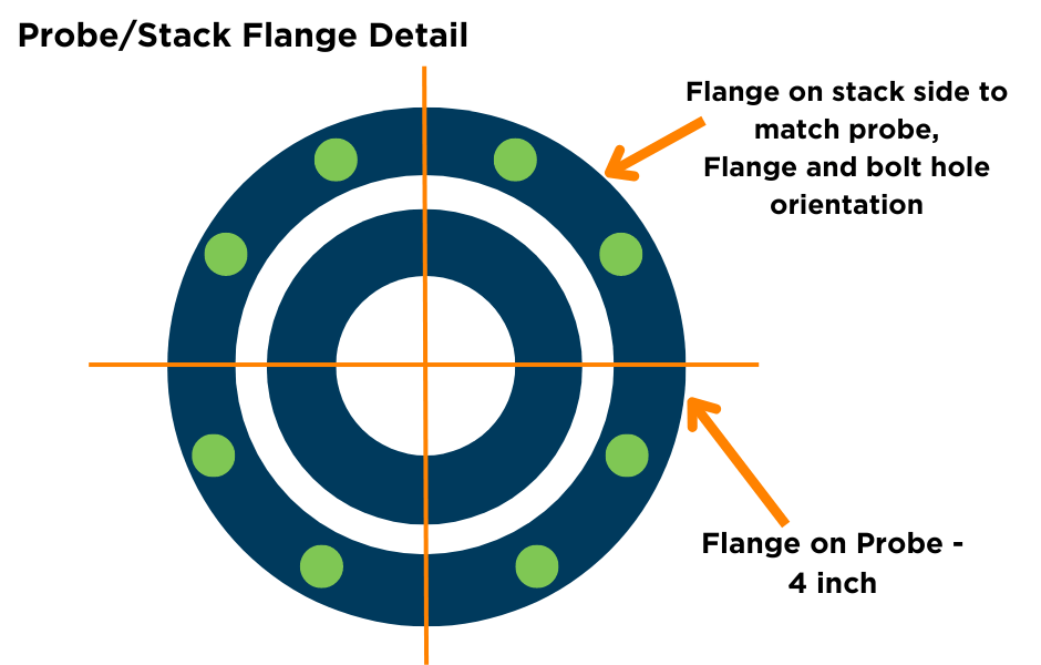
A mating flange on the probe matches the flange on the stack port. A gasket is typically used between the two for the best seal. Gasket material is selected based on stack conditions high-temperature stacks may need special gasket material.
EPA regulations determine the port location. The regs state: It is suggested that the measurement location be (1) at least two equivalent diameters downstream from the nearest control device, the point of pollutant generation, or another point at which a change in the pollutant concentration or emission rate may occur and (2) at least a half equivalent diameter upstream from the effluent exhaust or control device.
Internal Components of CEMS Probes
- Filter Housing: The probe filter keeps stack contaminants from entering the sample stream. Filter options include ceramic (2 & 5 microns), stainless steel (5, 10, 20 microns), or glass – the most commonly used ceramic. On each side of the filter are graphic washers to maintain an air-tight seal. The sample draws through the filter and into the sample line at a flow rate of approximately five lpm.
- Purge System: The purge system is used to blast compressed air through the probe at predetermined intervals to clean out any accumulated dust and stack contaminants. The compressed air is brought up the umbilical, fills a purge tank (40-60 PSIG), and then travels to a solenoid. The solenoid has a plunger triggered by a signal from the CEMS. When the solenoid opens, the compressed air is blasted into the filter housing through the filter and out into the stack – cleaning the filter and stinger. The application determines the frequency of probe purging. A gas boiler system, for instance, would be purged much less often than a coal boiler system. Frequency can run anywhere from once a day to once an hour. The purge length is also programmed in the CEMS and typically lasts 5-30 seconds. Besides being used for cleaning the probe, purge cycles are typically run between each cal gas during calibrations to clean out the line before the next cal gas is run.
- Cal Gas Port: Cal gas in a CEMS is introduced at the probe. Regulations state that the entire CEMS is calibrated – not just the analyzers. By introducing the cal gas at the beginning of the probe, the gas travels the same path as the sample. Calibration gas comes up a separate line through the umbilical. It is introduced at a flow rate higher than the sample (at least 1½ times the sum of the analyzer flow rates; typically 8-10 lpm). This allows only the cal gas to be drawn through the sample line down to the CEMS. The cal gas line from the umbilical connects to a port on the filter housing.
- Heater – The extraction probe utilizes a heater to keep the sample hot and prevent condensation. The heater jackets are band-type heaters attached to each side of the filter housing. A thermocouple is used to measure temperature. The temperature is controlled by a controller typically mounted in the CEMS cabinet. The temperature is normally set between 350°-400°F to prevent condensation of the sample in the probe.
Probe Utilities and Connections
Power is supplied to the probe through wires in the umbilical, eliminating the need for a separate power source on the stack. 115V is the typical voltage that powers the thermocouple and heater, and 24V powers the solenoid.
The umbilical is connected to the probe using a heat shrink boot, a 7″ length, 2.75″ min expanded I.D. nose. This is another step to ensure an airtight seal and protection from water infiltration at the probe box.
Continuous Emission Monitoring Probe Maintenance
The probe does not require routine maintenance for the filter head or the temperature controller. The filter element requires periodic replacement, depending upon application and dust loading. This is typically done during quarterly PMs.
Some customers prefer to use stainless steel elements which can be cleaned and reused.
They are cleaned in an ultrasonic cleaner with acid and flushed with a 50/50 solution of isopropyl alcohol and water to clean out the microscopic holes. Stainless Steel filters still need to be replaced every 1-2 years (dependent on application) because the microscopic holes eventually get clogged despite the cleaning (IPA does not dissolve the salts that build up).
The system will typically need a few hours to condition/stabilize after this is done.
How Can ESC Spectrum Help?
Are you looking to simplify and streamline your spare parts ordering process? If you manage inventory for your CEMS equipment, we can help.
We provide the CEMS parts you need fast with personalized service and a fast response time. We’ll include parts from any manufacturer on a single order and never include processing or hidden fees.
ESC Spectrum partners with key Continuous Emissions Monitoring (CEM) and process control suppliers to ensure our customers have access to the right equipment for their facility’s application. We have decades of expertise using CEMS and process control instrumentation from our suppliers to create custom-built new systems and repair, upgrade and maintain current systems. Our close relationships mean your plant gets the equipment it needs as soon as possible and at the right price.
More Resources
Interested in learning a more comprehensive overview of how CEM Systems work? Read Understanding Continuous Emissions Monitoring Systems (CEMS): A Comprehensive Guide. This guide will give you a complete understanding of all the components in the flow of a CEMS.