")
The Environmental Protection Agency clearly defines where ports for Continuous Emissions Monitoring Systems (CEMS) Probes, Flow Probes, and Opacity Units should be located on a stack or duct. This is called out in Title 40, Appendix B to Part 60 – Performance Specification 1 (Opacity), Performance Spec 2 (CEMS), and Appendix A (Flow).
In order to get good readings from any stack monitoring equipment and pass a Relative Accuracy test, the location where the sample is taken needs to be as representative as possible of the total emissions of the affected facility. Laminar flow is the goal, rather than trying to take a reading where stratification or turbulence might exist, which could give spurious readings. Each device has its own placement criteria.
Flow Probes
These have the most stringent regulations and require the longest straight stack or duct length.
Sampling and/or velocity measurements are performed at a site located at least eight stack or duct diameters downstream and two diameters upstream from any flow disturbance, such as a bend, expansion, or contraction in the stack or from a visible flame. If necessary, an alternative location may be selected, at a position at least two stack or duct diameters downstream and a half diameter upstream from any flow disturbance.
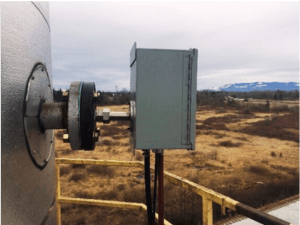
CEMS Probes
The following is what the regulations call out to help ensure a representative sample:
- CEMS: It is suggested that the measurement location be (1) at least two equivalent diameters downstream from the nearest control device, the point of pollutant generation, or other points at which a change in the pollutant concentration or emission rate may occur, and (2) at least a half equivalent diameter upstream from the effluent exhaust or control device.
- Point CEMS: It is suggested that the measurement point be (1) no less than 1.0 meters (3.3 ft) from the stack or duct wall or (2) within or centrally located over the centroidal area of the stack or duct cross-section.
- Path CEMS: It is suggested that the effective measurement path (1) be totally within the inner area bounded by a line 1.0 meter (3.3 ft) from the stack or duct wall, or (2) have at least 70 percent of the path within the inner 50 percent of the stack or duct cross-sectional area, or (3) be centrally located over any part of the centroidal area.
- Read more about CEMS Probes & How to Maintain Them
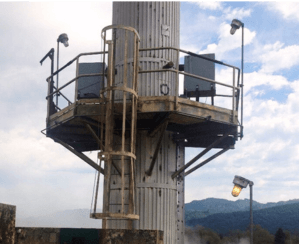
Opacity Ports
CEMS opacity port requirements are more stringent than the CEMS probe location but less than the flow probe.
Select a measurement location that is (1) at least four duct diameters downstream from all particulate control equipment or flow disturbance, (2) at least two duct diameters upstream of a flow disturbance, (3) where condensed water vapor is not present, and (4) accessible to permit maintenance.
It’s important to note that in all the criteria, there are exceptions that allow for stacks and ducts where there is not enough straight run to accomplish placement at 2, 4, or 8 diameters from a “last disturbance.” The main criterion is that a user must demonstrate that the location offers a representative sample.
For both CEMS and Flow, there are procedures spelled out where test points can be measured across a predetermined number of traverse points to find a representative location.
For opacity, “…you may select locations and light beam paths, other than those cited above, if you demonstrate, to the satisfaction of the Administrator or delegated agent, that the average opacity measured at the alternative location or path is equivalent to the opacity as measured at a location meeting the criteria…”
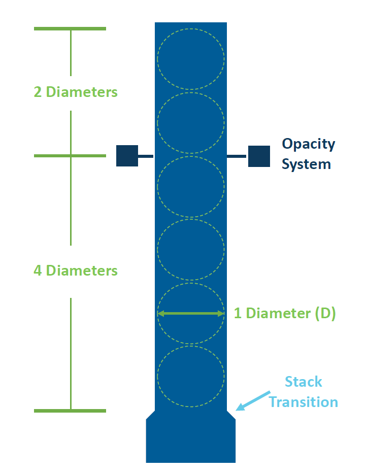
Here is a sample illustration showing how the equivalent diameters are measured on a stack or duct.
In Summary
Essentially a long run of straight stack or duct is needed after any disturbance, whether it be an ID fan exit, the beginning of a straight part of a stack after a transition, after an elbow, etc. How far down from that last disturbance is different for each instrument: the CEMS probe is two equivalent diameters, opacity is four, and flow is eight. In all cases, there should be 1-2 diameters after the unit of straight stack or duct before an exit, another elbow, or another device. Having these as a minimum will help ensure passing certification and RATA tests and make for fewer headaches all around with your compliance equipment.
Interested in learning more about CEMS Equipment? Check out our blog post, Continuous Emission Monitoring System: Upgrade or Replace?
ESC Spectrum partners with key Continuous Emissions Monitoring (CEM) and process control suppliers to ensure our customers have access to the right equipment for their facility’s application. We have decades of expertise using CEMS and process control instrumentation from our suppliers to create custom-built new systems, as well as repair, upgrade and maintain current systems. Our close relationships mean your plant gets the equipment it needs as soon as possible and at the right price.
We also provide services to streamline your RATA Testing Process with our RATAView™ software. Developed by stack testers for stack testers, RATAView was purpose-built to help meet the challenges of stack testing for an easier and faster testing experience while improving accuracy.
Contact Us Today for a free demo of our RataView Software or a quote on CEMS equipment.