Carbon Monoxide (CO) Analyzers
While more than one analyzer technology is available for measuring various Continuous Emissions Monitoring Systems (CEMS) gases, a long history of experience has shown that certain technologies lend themselves better to specific gases.
In this case, we look at using NDIR technology for the measurement of Carbon Monoxide (CO). NDIR offers reliability, stability, and sensitivity for accurate Carbon Monoxide (CO) measurement.
How NDIR Analyzers/CO Analyzers Work
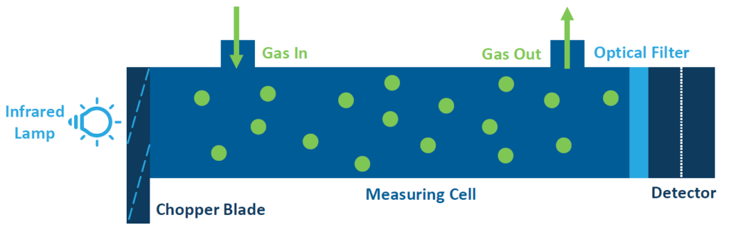
NDIR analyzers (also CO Analyzers) incorporate a single-beam photometric system and a detector with a microflow sensor. A microflow detector is a sealed unit filled with the same gas as the component of interest (CO in this case). The length of the sample cell determines the most sensitive range for the CO component. The infrared gas analyzer measures gas concentration based on the principle that Carbon Monoxide (CO) absorbs infrared radiation at a specific wavelength. The instrument consists of an infrared light source, a chopper, a measuring cell, and a detector filled with a gas mixture containing the gas component to be measured.
The infrared light source emits infrared light in all directions. The light emitted forward is transmitted and reflected into the detectors. The infrared light emitted backward is reflected by a reflecting surface and is added to the infrared light emitted forward.
Arranged between the infrared light source and measuring cell is a chopper blade that rotates to modulate the infrared light beam at a regular frequency. The modulated infrared light beam thus formed passes through the measuring cell. When this cell is filled with a sample gas, the light energy is partially absorbed or attenuated before it reaches the front chamber of the detector.
Both the front and rear chambers of the detector are filled with the gas component to be measured. The infrared light energy is partially absorbed in the front chamber and residual light is absorbed in the rear chamber, thereby increasing pressure in both chambers. This pressure difference between the front and rear chambers causes a slight gas flow to be produced through a path connecting these chambers with each other.
The slight flow is measured as an electrical signal by a micro flow sensor arranged in the path connecting the chambers with each other. The amplitude of the signal produced depends on the amount of light that reaches the detector. The maximum amplitude is achieved when zero gas is flowing in the measuring cell.
Subsequently, when CO from a sample (stack) is introduced into the cell, it absorbs a portion of the light, leaving less to be absorbed by the detector. With a lowered amount of light absorbed, the pressure created and resulting amplitude is lower. The difference in amplitude between the zero measurement and the measurement of a sample gas in the cell is correlated to a concentration of CO.
Connections & I/O for Carbon Monoxide Analyzers
Like other analyzers, Carbon Monoxide (CO) Analyzers have four basic connections (typically in the backplane). There is a sample inlet, a sample exhaust, a power connection, and a signal wire connection (normally an analog output corresponding to the sample value). Either a 4-20mA or 0-10V analog signal output is commonly used.
Many analyzers include digital outputs for alarm conditions, etc. Newer analyzers have an Ethernet output for direct communication with a PC.
Maintenance
Preventative Maintenance
Preventative Maintenance is recommended quarterly with any Carbon Monoxide (CO) Analyzer:
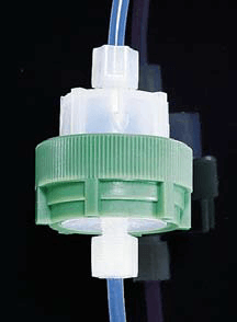
- A good practice is to install a final protective Teflon filter just before the analyzer inlet. The picture to the right shows a typical Teflon filter holder which holds a Teflon disk. This filter holder is simply unscrewed for filter replacement. This filter should be changed quarterly.
- Each analyzer should be calibrated to ensure accurate readings.
- The status of components can usually be checked through various menus on the analyzer display. There are features that display gain and pressure, etc. It is a good practice to record various analyzer values in a daily log. These can be checked for trends as different components start to fail or as an analyzer starts to plug. This log becomes invaluable for troubleshooting.
- Chassis filters and/or fan screens should be cleaned every quarter to keep dust from accumulating and building up inside the analyzer case. For more information, read The Key to Efficient CEMS Equipment: Check Your Filters.
- ESC Spectrum has many resources on PM including blog posts such as, CEMS Analyzers: What They Are and How to Use Them.
Additional Maintenance
There is very little additional maintenance specific to a CO analyzer:
Dust or water droplets entering the measuring cell may cause drift due to contamination. When it is impossible to adjust the zero level with the zero control mounted on the front panel, check the measuring cell for contamination. If contamination is present, check the sampling system, especially the filters, to eliminate the source of contamination. Periodic maintenance is generally not required. Cleaning is accomplished by use of a cleaning agent (such as isopropyl alcohol or household glass cleaner) and a non-abrasive, lint-free cloth or tissue.
There are other PM tasks that are done on an annual basis.
- The pump should be rebuilt with a diaphragm and valve replacement kit. This is inexpensive insurance.
- Bearings should be inspected. Rather than replace bearings, it’s easier to replace the entire pump.
- Replace any capillary o-rings and clean or replace any capillaries
How ESC Spectrum Can Help
Interested in learning a more comprehensive overview of how CEM Systems work? Read Understanding Continuous Emissions Monitoring Systems (CEMS): A Comprehensive Guide. This guide will give you a complete understanding of all the components in the flow of a CEMS.