What is a Monitoring Plan?
A monitoring plan is a detailed document that outlines periodic monitoring, compliance or corrective actions, and the methods used to collect air emissions data. It serves as a transparent record of the methodology employed in a specific installation, including data acquisition system activities. A monitoring plan encompasses various aspects, such as compliance, detailed methods, credible information, and action steps to monitor and report air emissions effectively.
Let's Break Down The Components
A monitoring plan consists of several key components that ensure accurate monitoring and reporting. These components include compliance with specific programs, reporting frequencies, emission units, emission points, monitoring systems, pollution control devices, and additional monitoring requirements. The plan is site-specific, tailored to each installation, and should be continuously reviewed and updated to reflect current operations accurately.
The plan will also include:
- Reporting Programs & Frequency
- Emission Unit Details (type, fuel, etc.)
- Emission Point Details (height, shape, material, etc.)
- Monitoring System details (components, formulas)
- Pollution Control Devices
- Supplemental Monitoring – MATS
Monitoring plans are typically organized into tabs or sections for clarity. Just like organizing files in a folder, these tabs help categorize different aspects of the plan. Common sections may include methods, component systems, qualifications, formulas, defaults, non-flow spans, flow spans, Rectangular Duct WAFs (Wall Effect Adjustment Factor), loads, location attributes, and unit characteristics Supplemental MATS.
The first tab we explore is the “Methods” tab. Within this section, various parameters to be measured are outlined. For instance, CO2, H2O, and mercury are highlighted as parameter type codes. We gain insights into how it is recorded by selecting a specific parameter, such as CO2. In this example, continuous emissions monitoring (CEM) is employed to measure CO2 levels directly. Additionally, the concept of substitute data is introduced, allowing for reporting when monitoring systems are temporarily unavailable or undergoing maintenance.
One essential tab in a monitoring plan is the “Components” section. Here, we discover the specific equipment employed for measurement, such as a box in your CEMS Shelter. Detailed information, including manufacturer, model, and serial numbers, and additional specifics like dilution details are provided.
Within the components tab, the “Analyzer Range” tab holds information regarding the equipment by offering settings and calibration information, which help obtain precise measurements.
The “System” tab describes the type of system installed at each site. This section encompasses a unique monitoring system ID and configuration details, providing valuable insights into how emissions monitoring is conducted. It also indicates whether the system is fuel-specific or non-specific, allowing for a better understanding of data interpretation.
In some cases, a unit may qualify for certain types of designations. This includes Low Mass Emitting (LME) Units. The unit utilizes different types of data for calculating emissions in a more simplified system. This tab notifies the EPA the unit has a special qualification.
The “Formulas” tab introduces the formulas for calculating emissions, featuring codes and associated text. This information clarifies the calculation process and ensures consistency in reporting. Conversely, defaults establish maximum and minimum values for various parameters, which help display accurate calculations.
The “Defaults” tab defines terms such as maximum or minimum values. They are defaults that aren’t used in calculations. These records can include emission factors, moisture content, and maximum potential values. This tab refers to how data is calculated and is very important to the plant’s monitoring plan.
Non-Flow Spans refer to emissions that are not from the stack. SO2, NOx, CO2, etc. are common gases measured. This tab provides information about the range and span of the analyzer. It is important they are referred to periodically.
In addition to non-flow spans, flow spans are essential to monitoring plans, contributing to accurate emissions tracking. While they share similarities with non-flow spans, they differ in terms of unit measurement codes and the types of measurements involved. Flow spans are often expressed in units such as million standard cubic feet of gas flow per hour, specifically in the context of stack flow.
Stack flow measurements can vary, including actual cubic feet or feet of stack flow per minute. Understanding the specific measurement units used is crucial for interpreting data accurately. Flow spans also involve reported and adjusted span values, typically reviewed annually to ensure data integrity and compliance.
Within monitoring plans, certain abbreviations and terms may appear, such as AR-ECT rectangular duct, which stands for Wall Effect Adjustment Factor (WAF). Wall effects can impact flow determination, particularly in rectangular ducts. WAF is calculated using a specific procedure and applied to stack flow if applicable, playing a role in accurate emissions measurement.
Unit loads are another vital component outlined in monitoring plans. They define the load range of a particular unit, specifying the minimum and maximum operating capacities. High, mid, and low load levels are often identified, providing insights into the unit’s typical operational range. These load details are evaluated before Relative Accuracy Test Audit (RATA) procedures to ensure proper testing at relevant operating conditions. The information is submitted to the EPA for compliance purposes.
Location attributes within monitoring plans refer to physical details of the emission stack, offering information about factors like ground elevation and stack height. Indicators such as duct indicators or stack-high bypass indicators provide additional physical details about the stack structure. These attributes visually represent the emission stack and are accompanied by beginning and end dates for reference.
Monitoring plans also encompass unit-specific details, shifting the focus from the stack to the emission unit itself. Each unit is defined with a designated name, such as G1, along with information about its operational history. Descriptions of unit types, such as dry bottom wall fire boilers, clarify the equipment being monitored. Tabs within this section delve into capacity, fuel types (represented by codes like C for coal and PNG for pipeline natural gas), unit controls, and program participation (e.g., acid rain, NOx, ozone, cross-state programs).
For units affected by mercury or Toxic Standards, additional tabs provide specifics about the monitoring methods employed. This includes information about stack testing frequency, such as quarterly testing for particulate matter. The presence of quarterly stack testing indicates the use of periodic tests rather than continuous emissions monitoring. Other parameters, such as hydrogen chloride, may also be addressed in these tabs, providing a comprehensive overview of the monitoring approach.
Monitoring plans feature specific dates, indicating the beginning of each method’s implementation. These dates provide a clear timeline and ensure that accurate records are maintained. If a method were to conclude, the end date would be documented accordingly.
Understanding Part 75 Monitoring Plans
One type of monitoring plan is the Part 75 Monitoring Plan, which addresses compliance with programs like the Acid Rain Program, Cross-State Air Pollution Rule (CSAPR), and Mercury Air Toxics Standards (MATS). Reporting may be necessary under one or multiple programs depending on the facility’s requirements. The Part 75 Monitoring Plan is an electronic document structured in XML format and comprises three separate data files: monitoring, emissions, and quality assurance. These files are managed through the Emissions Collection and Monitoring Plan System (ECMPs).
Exploring the ECMPs Client Tool
The ECMPs Client Tool is the electronic application used to create and submit monitoring plans, along with the QA and emissions files. It serves as the primary means for transmitting information to the Environmental Protection Agency (EPA) for the relevant programs. It is essential to note that upcoming changes, such as the introduction of ECMPs 2.0, will require users to adapt to the new system in the future. Read more about ECMPS 2.0 Re-Engineering updates here.
Creating & Evaluating a Monitoring Plan
Developing a monitoring plan involves careful consideration of various factors. Starting with an outline and considering operating and maintenance practices, fuel sampling and analysis, periodic emissions testing, and continuous monitoring are crucial steps.
This must be continuously evaluated to ensure compliance and error-free data submission. The ECMPs Client Tool includes built-in logic checks to assist in the evaluation process.
Are There Different Types of Plans?
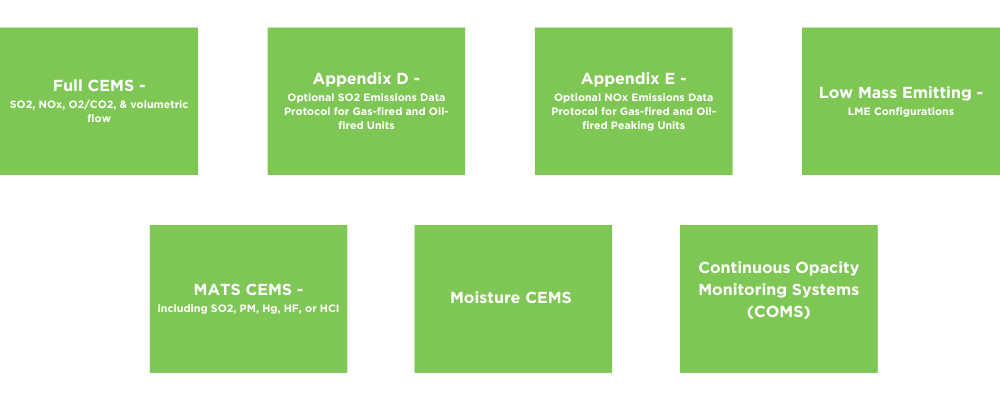
Monitoring plans can vary depending on the type of unit and specific requirements. Some examples include full CEMS, Appendix D, and Appendix II. Full CEMS are commonly used in coal plants and involve monitoring multiple emissions, such as SO2, NOx, and stack flow. Appendix D offers optional monitoring for certain emissions, allowing calculations based on fuel flow. Appendix II presents an alternative protocol for calculating NOx emissions using relevant data.
Overall...
Monitoring Plan records should be regularly updated to ensure they reflect the current operations and account for any changes in pollution sources or fuels, such as transitioning from coal to natural gas. It is important to consider load information, span and range values, and other factors to maintain the plan’s accuracy. Annual reviews are required to verify that the plan remains up to date, even if there are no significant changes. For example, if a turbine vendor proposes load increases, reviewing the monitoring plan and ensuring that the load parameters align with the proposed changes is necessary.
How Can ESC Spectrum Help
ESC Spectrum can assist you with your Monitoring Plan. Please contact us to schedule a consultation with our Regulatory Services team.
More Resources
Monitoring plans serve as a blueprint for accurately recording and reporting emissions data. Dig deeper into our webinar, “What’s In My Monitoring Plan?” on our YouTube Channel. With a site-specific approach and the ability to adapt to evolving strategies, these plans provide crucial insights into measuring and analyzing parameters. Read our blog post “Recommended Monitoring Plan Checklists” for some helpful information on guidelines and checklists to ensure your facility is compliant and audit-ready. Interested in learning more about regulations and staying in compliance? Read our Definitive Guide to Air Emissions Regulations.

Taylor Hempel - Marketing Specialist II
Taylor Hempel is a skilled marketer specializing in content creation, social media management, and driving customer engagement. With a BBA in Marketing from the University of Texas at San Antonio, she joined ESC Spectrum in February 2022. Taylor is adept at crafting informative content about continuous emissions monitoring systems, its components and data acquisition systems allowing her to craft content that educates and informs industry professionals.