Overview
Each CEMS integrator has their own preferences on CEMS components and design, and the following is merely an example of a recent Part 60 design from our Indianapolis facility. Designs and flow settings can vary based on customer preferences, regulatory factors and process conditions. There are several components to a Continuous Emissions Monitoring Systems (CEMS) operations with their own flow schemes. These are best broken down into:
- Sample Flow
- Cal Gas Flow
- Purge Air Flow
A gas sample originates in the stack and works its way through the system as described below, eventually exiting through the CEMS exhaust.
- Probe– The sample starts at the probe.
- Umbilical– The sample then flows down the umbilical to the CEMS cabinet.
- Sample Conditioner– Next, the sample is “pulled” through the sample conditioner by the CEMS sample pump. There is a filter after the sample conditioner and a flow meter to adjust the flow rate through the sample conditioner. The outlet rotometer is set to create a pressure of 6-10 psig on the control panel “Sample Pressure” gauge. As it leaves the sample conditioner, it is dry and ready to be introduced into the analyzers.
- Sample Control Panel –The CEMS has a sample control panel where all the rotometers are tied into the main sampling line for control of flow to each analyzer.
- Analyzers –The sample flow rate through each analyzer is different, depending on the analyzers’ requirements. Most analyzers are connected directly in-line after the pump, and each analyzer is set up with a flow regulator. This helps reduce the amount of flow introduced into the analyzer (typically, 1 lpm for O2, NOX and SO2, and 1.5-1.75 lpm for CO).
- Each analyzer has its own internal pump, except for O2 This is because the O2 analyzers operate at ambient pressure.
- Many NOX analyzers use an external pump because they need more vacuum, operate at a higher flow rate, and there is not room inside the analyzer for the larger pump.
- Exhaust – Excess gas is vented to an exhaust manifold located in the CEMS. A customer connects this to an outside drain line or exhaust. Caution must be taken to prevent this line from freezing, if vented to an area with low temperatures (i.e. drained to an outdoor location) – ice could build up, block the line, and allow water to back up into the analyzers.
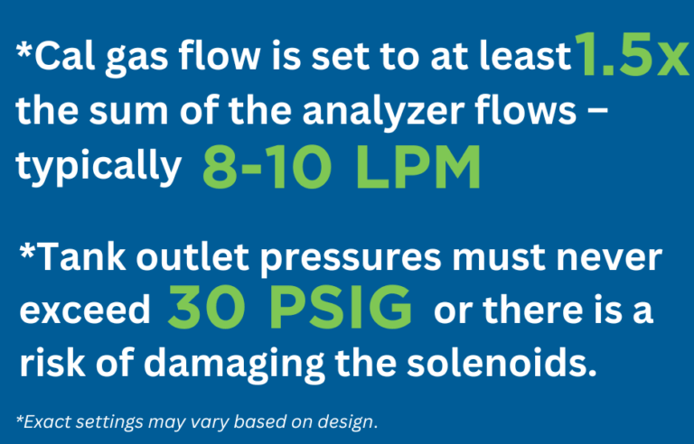
Cal Gas Flow
Cal gas is introduced into a CEMS at the probe tip and carried throughout the entire system along the same path as the sample. A solenoid is used to control the flow of each bottle. When the solenoid is opened, the cal gas travels through a second valve that allows it to go to the probe or bleed back out the vent. There is one final valve after the bleed valve which is used as a precautionary valve; it serves as a last means to make sure that no cal gas gets through, if one of the initial valves should leak. It is also used to depressurize the system after the cal gas flow to the probe is shut off.
Different materials for the regulators are used depending on what gases are in the bottles; gases are typically combined to minimize the number of tanks needed. Any of the gases that require a brass regulator can use a stainless steel regulator, but gases that require a stainless steel regulator cannot use brass.
Here are required regulators by gas type:
- Brass: CO, CO2, O2, Zero Air, Hydrogen-Air
- Stainless Steel: NOx, SO2, NH3
Cal Gas configuration is usually determined by compliance regulations.
- Daily – There are designated tanks for each gas and level required for the daily cal check. Both Part 60 & Part 75 systems require zero and span.
- Quarterly – There are designated tanks for each additional level required for the quarterly CGA (Cylinder Gas Audit) or Linearity Audit.
Purge Flow
To assist with keeping the sample clean and free of particulate build-up, compressed air (purge air) is used to “blow” out the probe periodically. This purge air originates from a customer-supplied compressed or instrument grade air line. The requirement is 80-100 psig at 8-12 scfm. The compressed air must be oil, particulate and pollutant free, with a dewpoint of less than -40°F.
Before the purge air goes up the umbilical, it is sent through an “Air Clean-Up” system. This panel further cleans the purge air of moisture and interfering pollutants. During the purge cycle, a solenoid in the CEMS cabinet opens to allow the purge air to bypass the sample conditioner and send it to the exhaust vent – this prevents damage to the sample conditioner.
Happy to Help
ESC Spectrum offers a full suite of CEMS solutions to keep your facility running smoothly and stay in compliance. Whether you need CEMS parts from our many suppliers, including extractive CEMS flow products, CEMS Maintenance services, CEMS integration, or Data Acquisition Software and services, we can help. Please get in touch with us to talk about your projects and get a quote.
Interested in learning a more comprehensive overview of how CEM Systems work? Read Understanding Continuous Emissions Monitoring Systems (CEMS): A Comprehensive Guide. This guide will give you a complete understanding of all the components in the flow of a CEMS.