What is a NOx Analyzer?
The NOx analyzer measures the concentration of nitric oxide, total oxides of nitrogen, and nitrogen dioxide. While more than one Analyzer technology is available for measuring various Continuous Emissions Monitoring Systems (CEMS) gases, a long history of experience has shown that certain technologies lend themselves better to specific gases.
According to the Environmental Protection Agency, this method of measurement “may be required by specific New Source Performance Standards (NSPS), Clean Air Marketing rules, State Implementation Plants, and permits where measurement of NOx concentrations in stationary sources emissions is required, either to determine compliance with an applicable emissions standard or to conduct performance testing of a Continuous Emissions Monitoring System (CEMS).”
One example is using Chemiluminescence technology to measure Nitric Oxides (NOx). Chemiluminescence offers the best sensitivity for low-range NOx measurement and is today’s most common method.
Chemiluminescence operates on Nitric Oxide (NO) and Ozone (O3) principles and reacts to create an energy that luminesces. Using a photomultiplier tube, the resulting light can be measured and correlated to a concentration of NO.
How Do NOx Analyzers Work?
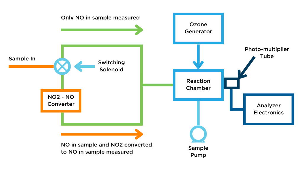
NOx is equal to NO + NO2. Because the chemiluminescence reaction only works with NO, Nitrogen Dioxide (NO2) must be converted into NO to be measured. NO2 is converted into NO using a molybdenum or stainless steel converter. Stainless steel is the most popular choice for converter material today, but the moly converter has been used extensively for years. The stainless steel converter is heated to 625°C. The oxide layer of the stainless steel “strips” one of the oxygen atoms off of the NO2, leaving NO.
The sample flows into the analyzer via a 3-way solenoid valve. This solenoid switches every 10 – 15 seconds. The solenoid valve routes the sample either straight to the reaction chamber, where only NO is measured, or through the NO2-to-NO converter, where NOx is measured (NO2 that’s been converted to NO and the NO in the sample).
Dry air is pumped in from the air cleanup through a flow switch into an ozone generator. The ozone generator generates the ozone needed for the chemiluminescent reaction. A flow sensor prior to the reaction chamber measures the sample flow.
In the reaction chamber, the 1-part ozone reacts with the 2-parts NO in the sample and luminesces. A photomultiplier tube (PMT) housed in a thermoelectric cooler set at -3°C (to eliminate any background noise) detects the luminescence generated during this reaction. The exhaust travels through the ozone (O3) converter from the reaction chamber to the pump and is released through a vent.
The difference between the resulting NO and NOx concentrations is used to calculate the NO2 concentration.
The internal pump serves three essential duties; it draws the sample through the analyzer, draws the ambient air through the ozone generator, and it maintains the vacuum for the reaction. Many higher-range analyzers require a larger pump which does not fit in the analyzer case and is mounted externally in the CEMS cabinet.
Pressure is monitored in the reaction chamber, and the values are adjusted using a pressure transducer. The analyzers are tolerant to changing atmospheric pressures to a degree, but since such small values are being measured, all variables are accounted for.
The air going to the ozone generator should be further dried before being introduced into the analyzer. This can be accomplished with dry air from the air cleanup drawn through a Nafeon© dryer placed before the ozone generator. Some analyzer systems use a canister filled with drierite just before the analyzer to remove any remaining moisture. Drierite is used more as an indicator versus a method of removing moisture.
Sample Pumping to Analyzers
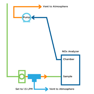
The sample pump in an extraction CEMS can create enough flow to “push” a sample into the analyzers. However, NOx Analyzers must operate under a vacuum and are very pressure-sensitive. NOx Analyzers have their own pump to “draw” a sample through and create the necessary vacuum.
In a CEMS, the sample is sent through a common manifold after the sample conditioner, bypassing lines to each analyzer. Before each analyzer is a rotometer to regulate the flow. There is a tee at the analyzer inlet, which allows the sample that’s needed to be pulled into the analyzer by the pump and any excess to vent through the exhaust.
Connections & I/O
All analyzers have four basic connections (typically in the backplane). There is a sample inlet, a sample exhaust, a power connection, and a signal wire connection (normally an analog output corresponding to the sample value). Either a 4 20mA or 0-10V analog signal output is commonly used.
Many analyzers include digital outputs for alarm conditions, etc. Newer analyzers have an ethernet output for direct communication with a PC.
Maintenance
Preventative Maintenance is recommended quarterly with analyzers:
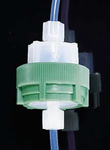
- A good practice is to install a final protective Teflon filter just before the analyzer inlet. The picture to the right shows a typical Teflon filter holder, which holds a Teflon disk. This filter holder is simply unscrewed for filter replacement. This filter should be changed quarterly.
- Each analyzer should be calibrated to ensure accurate readings.
- The status of components can usually be checked through various menus on the analyzer display. There are features that display gain and pressure, etc. It is a good practice to record various analyzer values in a daily log. These can be checked for trends as different components start to fail or as an analyzer starts to plug. This log becomes invaluable for troubleshooting.
- Chassis filters and/or fan screens should be cleaned every quarter to keep dust from accumulating and building inside the analyzer case.
There are other PM tasks that are done on an annual basis:
- The pump should be rebuilt with a diaphragm and valve replacement kit. This is inexpensive insurance.
- Bearings should be inspected. Rather than replace bearings, it’s easier to replace the entire pump.
- Replace capillary o-rings and clean or replace capillaries.
ESC Spectrum is Happy to Help
Interested in learning a more comprehensive overview of how CEM Systems work? Read Understanding Continuous Emissions Monitoring Systems (CEMS): A Comprehensive Guide. This guide will give you a complete understanding of all the components in the flow of a CEMS.